Impedance analysis
This approach analyses the filter sections from the point of view of the filter being in an infinite chain of identical sections. It has the advantages of simplicity of approach and the ability to easily extend to higher orders. It has the disadvantage that accuracy of predicted responses relies on filter terminations in the image impedance, which is usually not the case.[5]
Network synthesis
The network synthesis approach starts with a required transfer function and then expresses that as a polynomial equation of the input impedance of the filter. The actual element values of the filter are obtained by continued-fraction or partial-fraction expansions of this polynomial. Unlike the image method, there is no need for impedance matching networks at the terminations as the effects of the terminating resistors are included in the analysis from the start.[5]
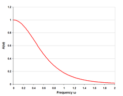
Here is an image comparing Butterworth, Chebyshev, and elliptic filters. The filters in this illustration are all fifth-order low-pass filters. The particular implementation – analog or digital, passive or active – makes no difference; their output would be the same.
Passive filters
Passive implementations of linear filters are based on combinations of resistors (R), inductors (L) and capacitors (C). These types are collectively known as passive filters, because they do not depend upon an external power supply and/or they do not contain active components such as transistors.
Inductors block high-frequency signals and conduct low-frequency signals, while capacitors do the reverse. A filter in which the signal passes through an inductor, or in which a capacitor provides a path to ground, presents less attenuation to low-frequency signals than high-frequency signals and is therefore a low-pass filter. If the signal passes through a capacitor, or has a path to ground through an inductor, then the filter presents less attenuation to high-frequency signals than low-frequency signals and therefore is a high-pass filter. Resistors on their own have no frequency-selective properties, but are added to inductors and capacitors to determine the time-constants of the circuit, and therefore the frequencies to which it responds.
The inductors and capacitors are the reactive elements of the filter. The number of elements determines the order of the filter. In this context, an LC tuned circuit being used in a band-pass or band-stop filter is considered a single element even though it consists of two components.
At high frequencies (above about 100 megahertz), sometimes the inductors consist of single loops or strips of sheet metal, and the capacitors consist of adjacent strips of metal. These inductive or capacitive pieces of metal are called stubs.
Single element types
The simplest passive filters, RC and RL filters, include only one reactive element, except hybrid LC filter which is characterized by inductance and capacitance integrated in one element.[1]
L filter
An L filter consists of two reactive elements, one in series and one in parallel.
T and π filters
Main article: Capacitor-input filter
Three-element filters can have a 'T' or 'π' topology and in either geometries, a low-pass, high-pass, band-pass, or band-stop characteristic is possible. The components can be chosen symmetric or not, depending on the required frequency characteristics. The high-pass T filter in the illustration, has a very low impedance at high frequencies, and a very high impedance at low frequencies. That means that it can be inserted in a transmission line, resulting in the high frequencies being passed and low frequencies being reflected. Likewise, for the illustrated low-pass π filter, the circuit can be connected to a transmission line, transmitting low frequencies and reflecting high frequencies. Using m-derived filter sections with correct termination impedances, the input impedance can be reasonably constant in the pass band.[2]
Multiple element types
Multiple element filters are usually constructed as a ladder network. These can be seen as a continuation of the L,T and π designs of filters. More elements are needed when it is desired to improve some parameter of the filter such as stop-band rejection or slope of transition from pass-band to stop-band.


